Pressure Washer Unloader Valve Diagram.
Pressured water must be cycled from the pump’s outlet side back to the inlet/water tank for bypassing, which is a very important process. Who do you think runs the show? A failsafe device known as an unloader valve.
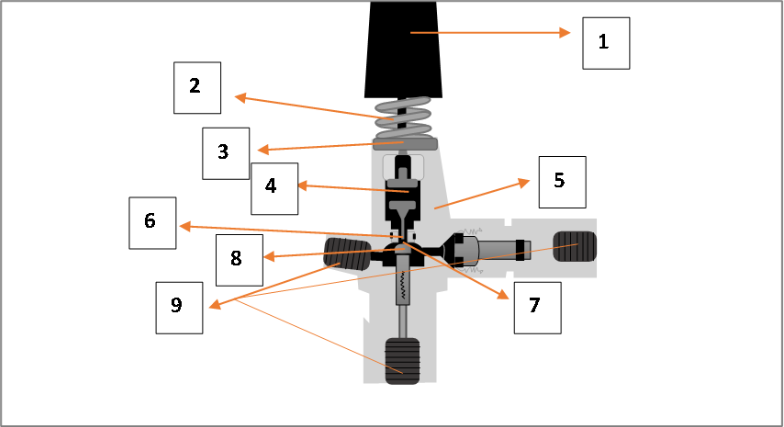
High tensile body, piston with seat stem and ball, washer, long spring, locknut cap, and other parts make up a pressure washer unloader valve.
Simply said, this mechanism relieves pressure on the water while the pressure washer is not in use, helping to prevent buildup. This is obviously a significant part to perform. This procedure, however, may be hampered by a number of different problems.
Maybe that’s why you’re here, looking at the pressure washer unloader valve diagram I just made for you. That’s not all, though; you’ll also need to know how the mechanism works. Have no fear, as it, too, shall be shown to you.
Table of Contents
The Pressure Washer Unloader Valve Diagram!
First, figure out where the unloader valve is for the pressure washer. The unloader valve is a safety feature that may be found on the pressure washer’s spout (the end of the hose where the two halves connect), just before the black cap.
The specifics of the role are hard to infer. And certainly not before now! For the meaning of the picture, scroll below.
Parts For Pressure Washer Unloader Valve
Let’s go right to the meanings of the parts in the above Pressure washer unloader valve diagram.
1 Stand for the Cap of the Lock Nut
It’s just a cover for two lock nuts (10 mm and 17 mm) and two ‘2’ pieces to keep them out of sight. This component not only prevents rust from forming on the metal surfaces but also maintains the proper water pressure.
2 Stand for Long Spring
The metal surface of this component is usually coated with a color to conceal it and increase its durability. In other words, it verifies the highest mechanical pressure that may be used to redirect the water.
3 Stand for Washer
Metal in construction, its sole function is to secure other components during surgery.
4 Stand for Inner Piston
It’s the main driving force behind the force’s expansion and directional change. This stationary part facilitates the transfer of high or low water pressure and is thus fixed in one location.
5 Stand for High Tensile Body
In the diagram, this may not stand out as much, but it is actually a protective casing for the unloader valve. It has a solid brass construction and a forged body.
6 Stand for Piston Stem
The diagram clearly shows that it is a small rod-like component that connects to the inner piston from behind. It merely ascends and descends to clear a channel through which water of varying pressures can flow unimpeded.
7 Stand for Piston Seat
This section remains between the “6” and the “8,” allowing the upper part to just rest on it without experiencing significant metal-to-metal contact or damage.
8 Stand for Piston Ball
This piece is designed to rest in the space between the number 6 and 8, allowing the top half to rest easily on top of it without causing significant wear and tear on the metal.
9 Stand for Inlet Ports (Optional)
There are essentially three exits—one each to the left, right, and bottom. The pump’s intake port is the leftmost one. The right one, however, is the drain hole. The last one is the escape hatch, or bypass port.
Pressure Washer Unloader Valve Mechanism
I believe having a basic understanding of how everything interacts will be useful for whatever use you have in mind for the graphic. So let’s begin!
I think whatever your need for the graphic is, a basic understanding of how all these components interact would be useful. Ok, let’s get started then!
First, you need to know why an unloader valve is used on a pressure washer. I think it’s obvious what has to be said there.
An unloader for a pressure washer acts as a shutoff valve, diverting the high-pressure water to a bypass for safety. And it achieves this by recirculating water from the pump’s exit back into the tank or intake.
The unloader can be thought of as a safety mechanism. The unloader valve on your pressure washer will open for one of two reasons, given the variety of valves available:
- As soon as the flow slows down.
- Or if there’s been a rise in pressure.
To fire, you must first pull the trigger. As soon as you accomplish that, the spring and the ball check mechanism will begin operating. The water flow into the bypass system starts to increase.
Both of these control the rerouting of water flow from the spray nozzle. Then it goes through a never-ending loop at the pump system’s input and exit.
This will continue so long as the wand trigger is not pulled again. When released, it stops the unloader flow actuation. This means that the water flow will now go via the nozzle.
Frequently Asked Questions
Can the pressure washer be used without an unloader valve?
Pressure washers do not require an unloader valve to function. However, doing so runs the danger of damaging the hoses, gun, and pump beyond repair if the PSI limit is exceeded. Since the unloader valve that normally channels the pressured water away from the system won’t be there.
How can I tell if my unloader valve is faulty?
In order to determine if your pressure washer’s unloader valve is broken, you can examine the signs of failure. Problems with the unloader valve might cause the pump to overheat and the engine to work harder than usual. There are a number of warning signals to listen out for, including engine noise, water leaks, and fluctuating output pressure.
Conclusion
I believe I have finished all of my notes for this tutorial with that. The pressure washer unloader valve diagram is provided to assist you in completing your task.
Also, if you’re trying something new, make sure you know how it works by reading up on the mechanism and the procedure in detail guides.