John Deere Hydraulic System Diagram- We Explained All-in-One For You!
Hydraulic system failures are challenging and confusing to figure out, not to mention finding an appropriate solution. However, in error detection, one can get some help from a visual demonstration.
That’s why we wanted to make it a priority for coming up with a John Deere hydraulic system diagram, one highly requested.
And finally, we have it. Today let’s go through the explanation for the whole system along with a little help on solutions to most common hydraulic system fails. Hope It Helps!
Table of Contents
John Deere Hydraulic System Diagram with Parts Details!
As we all know, the hydraulic system helps the lawn tractors (including John Deere) to improve the ride quality by using pressurized fluid. This system has tons of sub-parts in order to perform the task suitably. To know better, let’s look into the diagram of John Deere hydraulic system.
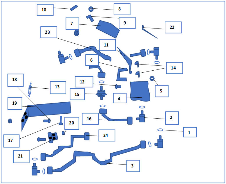
Learn More About Each Part:
1. O Ring
In the diagram of the John Deere tractor hydraulic system above, this looks like a rubber band that prevents the liquid or gas to enter the path. It sits right over the elbow fitting and keeps it secure.
2. Elbow Fitting
To confirm a nice flex point to secure the oil tube and hydraulic line, this does a great job. It let you easily route the tubes in 2 different directions in a limited room.
3. Oil Tube
It’s a small tube that conveys oil in a specific direction. This later connects to the lock nut using the elbow fitting and O-ring.
4. Pressure Relief Valve (PRV)
It is a handy part; most would know it as a relief valve that limits pressure. This also ensures the fluid is flowing at a specific level.
5. Lock Nut
This part is a threaded fastener that can be locked using another component. It performs greatly to secure the subject tightly so that this doesn’t vibrate or shake by resisting a loose feel.
6. Hook
Looks quite similar to U shaped tool, this part fits the lever into the pressure relief valve using 2 strong locking pins.
7. Quadrant
As you can see in the tractor John Deere hydraulic system diagram, this holds the lever with the knob, push nut, and insert.
8. Push Nut
This is an easy and cost-efficient fastener that needs a push to secure another component. It is suitable for fitting shafts and tubes.
9. Knob
To keep the lever, stay upright so that a driver can grip, this part helps a lot. It fits right above the lever and quadrant directly.
10. Insert
It is a pushing part that sits on the push nut and knob. It is mostly finished with brushing and ensures strength.
11. Lever
This part let you change the gear to high and low based on riding style. It fits on the relief valve through the single hook.
12. Pin Fastener
Also known as a steel pin that is a cylinder shape, this tends to keep the part aligned and joint tightly.
13. Extension Spring
The extension spring is an essential part of the hydraulic system that stores power and uses pulling energy among 2 gears. It works like elastic by keeping the two mechanisms close when they try to separate.
14. Spring Locking Pin
You can see the spring locking pin in the illustration where it works like a pin holding the hook with lock mechanisms.
15. Hydraulic Filter
This is an essential part of a hydraulic system that remove the dirt and particles to keep the oil clean for a continuous-time. It works rapidly when the pump and motor generate.
16. Tube
A tiny part that contains empty space inside to pass the fluids like gases and oils when hydraulic system working. It is mostly made out of metal or similar solid materials to carry the hot fluids.
17. Bolt
It is a fitting with a head and cylindric body to tread a component into the place. This needs the help of a flange nut to secure rightly.
18. Screw
Containing a large tread to twist inside the hole of the bracket, it holds the part in an appropriate manner. This confirms strong bonding and power by forming a solid seal. Mostly, it is made of wood and metal.
19. Bracket
A big frame that is probably made with solid material like metal which contains a lot of tiny holes in different directions. It usually secures the nut, screw, and bolt.
20. Flange Nut
Similar to ordinary nuts, it is made using a wider flange to work like a non-twistable washer. This simply enters into the tread of the bolt.
21. Clamp
It’s a small and versatile tool that holds and compresses the bolt and bracket using the flange nut in a solid seal.
22. Tie Band
As an OEM (Original Equipment Manufacturer) part, this rolls up another component. Nearly all tie bands are made with heavy-duty plastic or metal.
23. Hydraulic Hose
The hydraulic hose shifts the fluid of the hydraulic system inside different auxiliary and heavy-working components. It’s super flexible and armored to perform well if carrying high-pressure hydraulic fluids.
24. Hydraulic Line
Quite the same as the hydraulic hose, this part survives more heat and carries fluid in a specified direction.
Understanding The Hydraulic System Mechanism
In a tractor, the hydraulic system works in a certain way. There’s a transfer of fluid that pumps are in charge of making.
And it happens between the reservoir of the system and the hydraulic system of a tractor. So basically, what it does is that there’s an increase in pressure leading to an increase in fluid’s energy level.
The tractor uses a motor that plays the role of the principal power source of the pump to function. The hydraulic cylinder has a rod and piston. Under high pressure, the fluid gets the power to act upon hydraulic cylinder situated elements.
There’s the conversion of fluid power or pressure into mechanical work or force. Here the cylinder’s strokes basically conduct that conversion. As soon as there’s a retraction, fluids will go back to the reservoir.
And this triggers the cooling down of the reservoir’s fluid. As the metal walls allow heat to escape. Eventually, there’s a reduction of pressure as well. It also helps to remove any trapped or dissolved air from the fluid.
Common Hydraulic System Failures to Know About
There are quite a few days in which the hydraulic system can start erupting its regular functioning. And this segment is all about that. It shall keep you alarmed about what errors to watch out for that are corresponding to the hydraulic system. And perhaps a solution as well to keep those aside.
80% of Hydraulic Failures Happens Because Of
Contamination. And it could be both air and water. Both of these types of contamination can take place for one or more reasons, which commonly are:
- Breaches in system
- Pumps being damaged or fully unusable.
- Malfunction of the temperature.
Now talking about air contamination, it actually is just the air entering the hydraulic system. And it can be of two kinds.
Aeration and Cavitation
Now both types are equally damaging to the entire system. And by that we mean, you are going to notice some severe:
Hence you must have some good knowledge of the symptoms that indicates there are any of these types of contamination attacking the hydraulic system.
If we try to have a closer look at aeration, it is basically air entering the pump cavity. And it can enter from any outer source. Most of the time a loose connection is responsible. Or it could be due to leaks as well.
Best Way to Identify Aeration – The running pump will make a knocking-like sound most of the time.
Moving onto cavitation, this is basically the pump pulling out any dissolved air from the hydraulic oil and then imploding. This is not good for the pump’s overall health. And eventually causes damage to the pump as well as any surrounding components over time.
Best Way to Identify Cavitation – The hydraulic pump will make a whining-like sound.
Regarding water contamination, the most common reasons behind it happening are:
Water contamination is dangerous for the components of the hydraulic system. Those will degrade gradually if you don’t take the right measurement soon enough.
Best Way to Identify Water Contamination – The hydraulic fluid will have a milky appearance.
Thinning, Oxidization, and Thickening of Fluid Are Problematic
With passing time, the temperature changes that take place in hydraulic systems can lead to severe problems. It cannot be running too cold or too hot.
Things that indicate issues due to temperature malfunction are thinning, thickening, and oxidization of fluid.
Due to heat, hydraulic fluids can experience severe thinning, which is called fluid thinning. And this will cause:
- Interruption with the proper lubricating process.
- Fluid will become more prone to leak.
The hydraulic fluid can also thicken and oxidize due to too much heat in the system. And if that happens then:
Finally, fluid thickening, which means the hydraulic oil viscosity reduction due to the temperature being too low. And this can result into:
Usually, the main reason for such a problem is the bad heat dissipation ability of the system. This causes a build-up of heat and also can be responsible as an environmental factor for systems that are too cold.
Poor Quality & Level of Fluid
Another extremely common reason behind hydraulic failures is the low quality of the fluid as well as the level being poor. Due to poor filtration, the system can experience bad air contamination. The same happens with low fluid levels.
And that’s why using the right sort of fluid is so important. Keep in mind that there are specific hydraulic oils meant for certain kinds of applications, and you need to be choosey based on that.
Today you can even find oil options that provide resistance to any problem caused by temperature malfunction. There are also variants of oil that prevent any wear or foam additives. So that there’s less wear and air contamination.
Failures Due to Wrong Usage
Now, this is more the type of error that happens due to the carelessness or ignorance of the user. In fact, many hydraulic failures have it as the base reason.
The first one is the improper installation of a hydraulic system consisting of components. A very common example is having the pump shaft installed in such a way that it turns in the wrong direction.
And this basically is an open invitation for pressure build-up. The same goes for improper fitting of any pipe. Leaks are bound to happen after that.
Issues can also take place due to installing a part that is a mismatch for the system. And this leads usually too severe functional failures if not serious damage. For instance, if you get a motor for the pump that exceeds the maximum drive speed.
And the final factor would be simply being careless on usage and impatience overall. If you frequently operate the system beyond its capabilities, then facing trouble is natural. Also, a system that does not get enough maintenance will sooner than later fail.
Now if you have no clue about the right usage and maintenance, it’s high time you educate yourself on that. To help you, we will add sections next, so don’t worry!
Troubleshooting The Hydraulic System – Briefly Explained
Now, this is just one step extra that we’d like to take so that you find it easier to identify the failures with your John Deere. Some of the fundamentals for checking the whole system every now and then are what we are planning to cover.
Follow Up with Prevention & Maintenance
- Before purchasing any part, always double-check the specification so that there’s no chance of buying something unmatched.
- If you are trying to get new equipment, it’s best to first consult with an expert and take their opinions regarding it. Industry professionals have an eye on noticing tools that work well for users.
- You can invest in products meant for hydraulic system protection. There are many that help in preventing failures. For example, a locking actuator can be a great purchase. It will stop moving as soon as the failure is detected.
A Helpful Tutorial You May Need!
Frequently Asked Questions (FAQs)
Are John Deere hydraulics open or closed?
In John Deere, commonly the closed center system is more used. And this is seen mainly are the 2 cyl ones.
What is the difference between open and closed hydraulic systems?
The pressure stays intermittent while there’s continuous flow with an open center system. However, with the closed center system. You’ll find that the pressure stays continuous while there’s an intermittent flow.
How does a closed center hydraulic system work?
The control valves will receive a full pressure supply from the closed center circuits. And this does not depend on the fact whether the valves are actuated or not. There will be varying flow rates notable in the pumps.
And until the valve is actuated by the operator, the hydraulic fluid will experience little pumping. There’s no need for a return path that is open center towards the tank for the spool of the valve.
Wrapping Up
And there you have it. Hopefully, the John Deere hydraulic system diagram along with all the information about it would help you further in solving whatever issues you are facing with the significant system.
However sometimes even with enough resources, it still stays hard to come up with a solution. And if that’s what is happening with you as well, don’t hesitate to give a call to a professional.
Consult with them and find out the solution way quicker as well as it will be reliable.
